SYSTEM OF U AND Q REGULATION
The system of U and Q regulation is a set of hardware and software tools that make it possible to achieve the desired benefits in the controlled power system. The regulatory activity itself can be provided by means of these following devices (called action members):
• Generators of all types of power plants
• Compensation devices - static and rotary compensators, power reactors
• Transformers
It can be generally said the systems of U and Q control are mainly designed in a three-level hierarchy. Each of these levels has within this regulatory system other functionality, the time period of operation, location in a specific technical devices, administrator and the way of maintenance, operation conditions, etc.
The basic scheme is shown in Figure 1
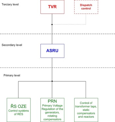
Fig. 1 – System of U and Q regulation
1. Tertiary Voltage Regulation (TVR)
Objective: The calculation of optimal distribution of reactive power flow in the regulated power system and of the set voltage values in the pilot nodes of the power system. Pilot node means the bus-bar of the transformer substation or distribution substation of the electricity system, in which the supply of reactive power is possible to control.
Characteristics: The highest level of the voltage and reactive power control. TVR is implemented by means of the computational function that belongs to the category of higher dispatching control functions. Specifically it is the computational task of the Optimal Power Flow type (OPF), which uses the estimated data for its calculation.
Placement: Implemented in the control system of the dispatch center
Triggering: Periodically in few-minute intervals (e.g. 10 minutes) or in the instant of significant event development in the system (e.g. change of interconnection of the system, etc.).
Note: TVR may not always be realized only as an on-line function in the control system of the dispatch center, even if it is the best solution. In some systems there is the off-line optimization calculation performed during the preparation operation or the calculation is temporarily replaced by the dispatching instruction or by operational decisions of the dispatcher that can have a consultation program at his disposal.
2. Automatic secondary voltage regulation (ASRU)
Objective: Maintain the pilot node voltage in the set voltage tolerance (e.g. 0.5 ÷ 1 kV).
Characteristics: Middle level of regulation. ASRU consists of a separate device (see Figure 2). It works on the principle of the regulator with negative feedback.
Placement: Decentralized ASRU - whole system of ASRU in the power plant or substation
Centralized ASRU - partly in the dispatch center of the transmission or distribution system and partly in the power plant.
Triggering: The interval between two regulatory interventions is usually set to be 18 to 20 seconds. However, each originated regulatory deviation has to be eliminated within 120 seconds after its creation and regulatory process must be aperiodic with no more than one overshoot.
Note: From a technical point of view it is suitable for the ASRU if uses for elimination of voltage deviations all the significant action members connected to the regulated pilot node. ASRU must respect all the technical limiting conditions of the power system as well as of the individual action members involved.
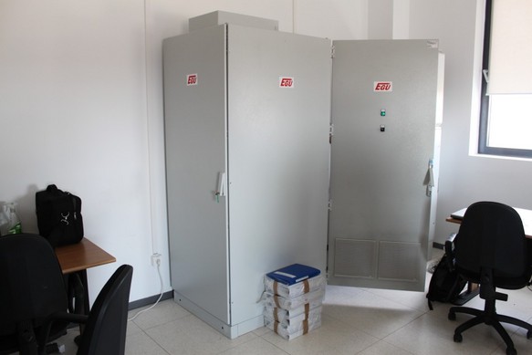
Figure. 2 - Switchboard cabinet of the Automatic secondary voltage regulation
3. The primary voltage regulation (PRN)
Objective: To realize a change in reactive power supply into the power system according to the ASRU commanding
Characteristics: The lowest level of regulation.
Placement: On the individual action member - the power production block, transformer or the means compensation.
Triggering:
Note: Into the primary voltage regulation within ASRU is generally possible to involve virtually all the types of power plants connected to the regulated power system (fossil power plants, hydropower plants, wind parks and photovoltaic power plants, atc.). The specific choice depends on their technical equipment and their owner´s willingness to cooperate with the power system.
Doplňující obsah
Contact
Ing. Jaromír Beran, CSc.
EGÚ Praha Engineering, a.s.
T: +420 267 193 436
M: +420 603 229 161
E:
http: www.egu-prg.cz