VOLTAGE AND REACTIVE POWER REGULATION
The general power system is characterized by almost constant supply of reactive power of all the power plants involved in this system and by permanent, greater or lesser voltage fluctuations in the nodes (substation busbars) of the power system.
Voltage fluctuation is resulting from the dynamic nature of the power system and its most common causes are:
- Switching on, switching off and switching over the lines and transformers.
- Switching on, switching off and regulation of electricity consumption.
- Switching on, switching off and control of electricity generating power plants or their parts (blocks).
- Different types of failures in the electricity power system, which usually lead to undervoltage in the system.
- Improper selection, setup and coordination of the various types of compensation and control equipments.
Voltage fluctuation occurs at all voltage levels of the electricity system and is transmitted up to the end customer of electricity and adversely affects its quality. Fluctuation of voltage also has a negative impact on power system operation efficiency and security of supply of electricity supply to the end customers.
The difference between the power system without the U and Q regulation (unregulated system) and the power system with regulation of U and Q (regulated system) is graphically presented on the example of 400 kV substation into which a large wind park is involved.
In Figure 1 there is plotted a daily record of the voltage on the bus-bars 400 kV of the observed substation for the case of U and Q regulation being switched off. Voltage 400 kV changes in a wide range depending on the current situation in the power system.
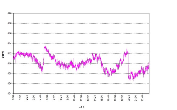
Figure. 1: Unregulated system - the voltage of 400 kV
In Figure 2 there is plotted the course of a daily supply of reactive power from the monitored wind farm to the substation 400 kV for the case of U and Q regulation being switched off. This course is almost constant and shows that the wind farm does not participate in the stabilization of voltage in the system. The reactive power supply is the same at all voltage values in the system.
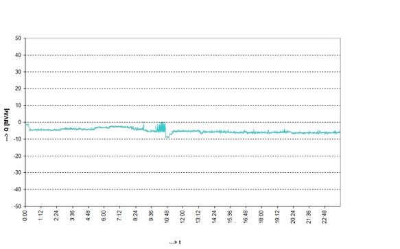
Figure. 2: Unregulated system - course of the wind farm reactive power
In Figure 3 there is plotted a daily record of voltage on the bus-bars of 400 kV substation monitored when switched on U and Q regulation. The controlled voltage 400 kV is maintained within the tolerance band of ± 0.5 kV of the voltage setpoint of 400 kV by means of changing the reactive power supply from the wind farm. During the day, the set value of 400 kV voltage was changed in a few cases to follow command of the dispatch center according to the current needs of the regulated system.
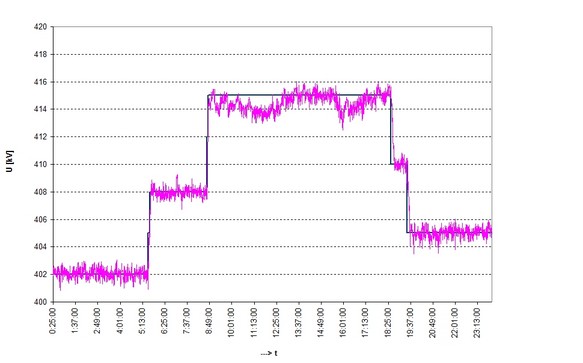
Figure. 3: Controlled system - the course of voltage of 400 kV
In Figure 4 there is plotted the course of a daily supply of the active and reactive power to the monitored wind farm substation 400 kV. The figure shows:
- The absolute independence between the physical delivery of active and reactive power from the wind farm. These two outputs do not affect each other.
- The necessity of significant changes in reactive power of the wind farm for keeping the set value of 400 kV voltage
From a comparison of Figures 3 and 4 it is also seen the physical independence between the voltage and active power.
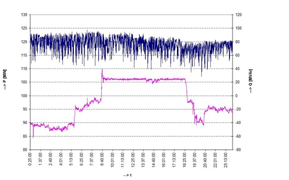
Figure. 4: Regulated System - the course of active and reactive power wind farm
Doplňující obsah
Contact
Ing. Jaromír Beran, CSc.
EGÚ Praha Engineering, a.s.
T: +420 267 193 436
M: +420 603 229 161
E:
http: www.egu-prg.cz